 |
| July 10, 2012 | Volume 08 Issue 26 |
Designfax weekly eMagazine

Archives
Partners
Manufacturing Center
Product Spotlight
Modern Applications News
Metalworking Ideas For
Today's Job Shops
Tooling and Production
Strategies for large
metalworking plants
Energy-plant starts/stops are tough on steam components
TÜV NORD uses Abaqus to predict fatigue and fracture and to optimize power plant cycling and operations.
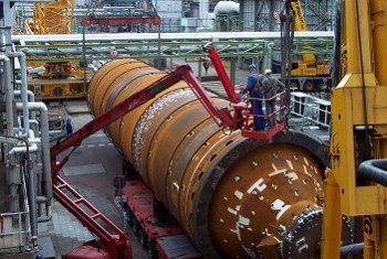
Two aging chemical manufacturing process vessels, with cracks that had developed from extreme temperature shifts, were removed and analyzed by engineers from TUV Nord. The team took physical measurements of the cracks and compared the results to their FEA crack propagation calculations for components in steam-generating power plants, finding good agreement.
Conventional coal and gas power plants were not designed to navigate the production peaks and valleys of today's energy landscape. Originally built to produce continuous power, they are increasingly being used as backup to supplement sustainable forms of energy, such as wind and solar, which are playing a more important role in the power mix. But since the wind doesn't always blow and the sun doesn't always shine, energy providers need to constantly toggle steam-generating plants from off to on and back again.
Such starts and stops are quickly becoming the new standard for energy companies. Operating under these conditions means greater stresses on the entire power plant, but especially on the thick-walled, main steam-line components through which steam is transported from the pressure vessel to the turbine and where the greatest temperature shifts occur. Plant start-ups, when most extreme, can involve a temperature increase in these components of almost 500°C in an hour. A shut-down is almost identical, but in reverse. To ensure that overall power generation remains constant enough to meet varying demand, the number of start-stop cycles will rapidly increase in the future.
With frequent steep temperature cycling, system components such as the vessel, valves, and header are subject to fatigue and fracture. As a result, their lifespan may be shortened, negatively affecting operational efficiency, system maintenance, and energy production.
For Axel Schulz, the coordinating engineer on the stress calculation and design team at TÜV NORD SysTec in Hamburg, Germany, evaluating and solving the engineering challenges of temperature cycling for the power and chemical industries is a primary focus. These projects have taken on even more importance recently following passage of a new energy program in Germany.
"The German government has established an ambitious plan to replace nuclear energy with wind and solar power by 2022," says Schulz. "To compensate for the fluctuating power production of the newer technologies, we have a critical need for fast-cycling power plants." As the energy industry gradually becomes greener, it's likely that this trend will be repeated worldwide.
FEA guides improvement of power plant operations
In response to such changing conditions, TÜV NORD created a Cycle Optimized Operation (COOP) program designed to improve facility standards, performance, and management. "When evaluation and testing closely reflect reality," says Schulz, "plant operation and cycling can be made much more efficient and costs can be controlled."
Realistic simulation with Abaqus finite element analysis (FEA) software from Dassault Systèmes' SIMULIA brand was chosen as the core solution for the COOP concept. "Abaqus has very sophisticated capabilities for analyzing fluid structure interaction, fracture, and fatigue," says Schulz. "It also has advanced tools for calculating crack propagation."
German regulations for power plant operation are not only strict, they are extremely conservative and based on over-simplified assumptions: currently, start-up and shut-down processes are calculated as approximately quasi-static operating procedures, and heat transfer coefficients are not used (the steam temperature is set equal to the wall temperature). Due to these simplifications, according to Schulz, fatigue and damage to parts and components can be significantly overestimated.
In the first module of the COOP's two-part process, TÜV NORD engineers use Abaqus fluid structure interaction (FSI) capabilities to simulate real-world heat transfer conditions within plant components. This results in more realistic assessments of component stresses and less conservative design codes.
In the COOP's second module, the Abaqus FSI simulations enable optimization of the plant component's interior shape to reduce pressure losses, stresses, and noise emissions. This module also uses extended finite element methods (XFEM) and crack propagation analyses both native to Abaqus to calculate crack geometry and growth. These analyses allow the engineering team to determine new safety standards and more accurately evaluate service life.
"Using simulation, we can recommend better regulations and suggest more accurate inspection intervals, eliminating unplanned maintenance and costly repairs," says Schulz.
Putting the COOP program into action
To evaluate the COOP program methodology, the TÜV NORD team carried out an analysis of two aging chemical process vessels (components used in chemical manufacturing that also undergo frequent cycling and extreme temperature shifts). "We chose to study these vessels because we provide services to the chemical industry, and these process vessels have operating conditions that are a good match for main steam-line components in fast-cycling power plants," says Schulz. The vessels selected for the study also had developed some cracks, so the engineering team could compare FEA results with physical measurements.
The process vessels were constructed with skirt support expansion joints manufactured out of creep-resistant steel and designed to minimize thermal loading during cycling. During start-up, a 490°C medium was added to the vessel, elevating the temperature 135°C in only 15 min. During shut-down, cold water at 50°C was fed in, cooling the vessel's contents by 250°C in 45 min. The vessel was subjected to the stresses resulting from these extreme temperature changes approximately 200 times per year, or once every 33 hr (see Figure 1).
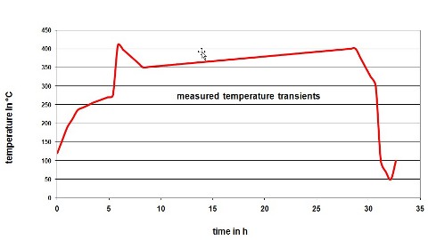
Figure 1. Graph shows a complete 33-hr start-up/shut-down cycle for a chemical process vessel that has extreme temperature shifts of 135°C in a 15-min start-up window and 250°C in a 45-min period during the shut-down process. This cyling is very similar to that found in steam-generating power plants, which are being used to provide back-up power for wind and solar facilities.
As a result of this frequent and extreme cycling, cracks had developed in all 82 expansion joints, all at the same position, varying in length and depth depending on time of service. For the simulation, TÜV NORD engineers were able to model just a 15-degree sector of the process vessel, because of its symmetrical shape and relatively constant operational load.
As part of the COOP's first module, the team carried out a sequentially coupled temperature-stress analysis. (In this special case, an advanced FSI-calculation was not necessary.) They set up this simulation using real-world operating values for temperature (heat transfer), mass flow (speed), and pressure, as well as actual component geometry. The results indicated that a stress maximum of approximately 1,150 MPa occurred on both heat-up and cool-down when the temperature transient was steepest (see Figure 2). Using fatigue curves of test rods (made of materials similar to the process vessel) subjected to load cycles, the lifespan of the component was calculated to be 400 cycles (or approximately two years).
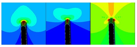
Figure 2. FEA of the stress distribution around the expansion joint of the process vessel skirt support shows equivalent stress (left), circumferential stress (center), and axial bending stress (right).
In the COOP's second module, the engineering team used the results of the real-world stress calculation as a starting point and performed a shape optimization by changing the contours of the expansion joints (the same technique can be used on a vessel contour). They determined that minor changes in shape can deliver significant improvements in fatigue strength and that as geometries are modified to improve flow, the resulting pressure losses and local bending stresses can be reduced.
To further understand the interactions between vessel stresses, fatigue, crack geometry, and crack propagation, the team used the XFEM capability in Abaqus coupled with contour integral calculations. "The XFEM method makes it possible to study crack growth across elements in a way not possible before," says Schulz. "The contour integral calculation gives us the ability to analyze stress intensity values for a series of crack depths and shapes." These analyses showed that the greatest stress occurs when the vessel is most rapidly heating up, that the stress decreases with increasing crack depth, and that the crack grows more rapidly on the outside than the inside of the frame connector (see Figures 3 and 4).
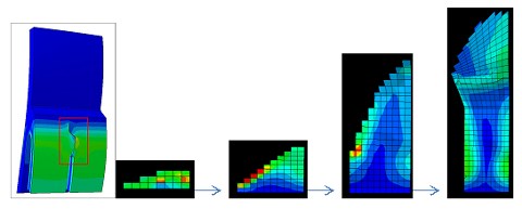
Figure 3. Abaqus extended finite element method (XFEM) shows a progression of increasing crack growth (left to right), starting in the area of interest on the process vessel's skirt support expansion joint. Dominant circumferential stresses cause a crack to form at the end of the expansion joint. Due to uneven stress in the frame connector above the joint, the crack grows more rapidly on the outside than on the inside of the connector.
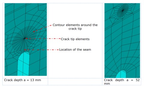
Figure 4. A series of contour integral calculations for various crack depths and shapes (depth is 13 mm on left and 52 mm on right) were carried out using Abaqus in order to calculate stress intensity values. Crack depth can be varied with only a few adjustments.
The team then compared their simulations with physical testing using strain gauge and crack measurements on the vessels themselves to verify the Abaqus FEA results. "With both stress distribution and crack growth, we found very close correlation between Abaqus results and the measurements," says Schulz. "It became apparent that, at a high number of cycles, crack growth was being overestimated."
Simulation provides a clearer view
For TÜV NORD, realistic simulation has created a window into the black box of power plant operations. With a better view and enhanced understanding of the stresses of thermal cycling, the engineering team can make recommendations to power providers about optimizing power plant cycling processes and system component designs.
According to Schulz, improvements include the nuances of ramp-up and ramp-down rates, as well as more precise timing of maintenance, service, and inspection cycles. Also, component designs can be modified for greater lifespan. For example, lowering the stress and fatigue level of a main steam-line valve could save as much as 200,000 euros in replacement costs. The COOP program is designed to minimize and manage unplanned equipment repair and reinvestment such as this.
"Since early 2011, we have been using the COOP process in Germany, and we'll soon be using it with both energy and chemical industry customers worldwide," says Schulz. "By incorporating advanced FEA tools into our methodologies, we are helping create more reliable and flexible power plants."
Such flexibility will likely become a required capability for energy companies seeking to navigate the peaks and valleys of the future power grid.
Learn more about Abaqus from SIMULIA by clicking here.
Published July 2012
Rate this article
View our terms of use and privacy policy